935
Views & Citations10
Likes & Shares
This paper focuses on the design of an ultra-wide band (UWB) printed circuit antenna of enhanced performance in terms of gain and radiation patterns with the aid of meta-material (MTM) structures. The antenna patch is shaped as a miniaturized open mouth flower backed with a partial ground plane to provide a significant enhancement in the antenna bandwidth. To provide a stable antenna radiation pattern over the entire frequency band, a MTM structure is introduced at the edge of patch structure. The proposed MTM unit cell is constructed from three arrays of H-resonators. Such arrays are provided to focuses the antenna radiation patterns toward the end fire of the antenna. The MTM characterizations in terms of effective constitutive parameters are retrieved with in the frequency band of interest. Numerical simulations are conducted using CST MWS and HFSS software packages to arrive to the optimal antenna design based the proposed MTM structure. Finally, the optimal antenna design is fabricated and tested experimentally for validation.
Keywords: Keywords: UWB, MTM, Partial ground
INTRODUCTION
C = B log2 (1+SNR) (1)
where C denotes the maximum transmit data rate and B stands for the channel bandwidth. Equation 1 indicates that the channel capacity can be increased rabidly by increasing the bandwidth occupation or transmission power [9]. However, the transmission power, i.e., SNR, must not be increased significantly because many portable devices are battery powered and the potential interference consolation [10]. Therefore, a large frequency bandwidth would be the feasible solution to achieve a high data rate [8]. The Federal
Communications Commission adopted the commercial operation of ultra-wideband (UWB) technology [3].
AN UWB ANTENNA BASED MTM STRUCTURE DESIGN
In this section, a numerical study based on Computer Simulation Technology Microwave Studio (CST MWS) formulations [11] is invoked to optimize the antenna performance and the MTM characterizations. In the first, the antenna structure is optimized to provide the maximum antenna bandwidth match with maximum gain. Next, the MTM is designed and characterized numerically in terms of S11 spectrum. Then, the antenna structure is integrated to the MTM to realize the obtained enhancements on the antenna performance.
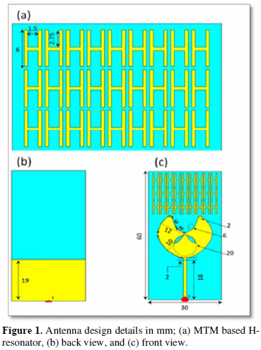
A partial ground plane micro strip antenna of a flower-shaped patch with an open mouth cut is designed for the UWB applications. The patch structure is fed with a micro strip line of a varied width from 1 mm up to 2 mm following a binomial transformer [12,13].
The patch layer is mounted on an FR-4 substrate of 30 mm × 60 mm with 1 mm thickness. The partial ground plane is introduced to obtain the maximum bandwidth coupling over the entire band of interest. Therefore, the antenna bandwidth is found to cover the frequencies from 2.4 GHz up to10 GHz with maximum gain of 5.9 dBi. However, the antenna radiation patterns would be mostly scattered toward different directions that limits the antenna use in portable and compact handsets devices. In Figure 1, the antenna design based on MTM structure is presented.
AN UWB ANTENNA BASED MTM STRUCTURE DESIGN
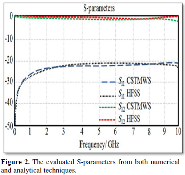
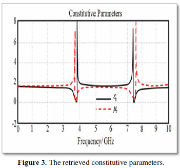
The unit cell structure is characterized in terms of S-parameters to retrieve the constitutive parameters in terms of relative permittivity (εr) and relative permeability (μr). As seen in Figure 2, the S-parameters are evaluated from CST MWS, than, they are compared the HFSS results. This comparison is performed to validate the obtained results from the CST MWS software package.
THE OPTIMAL ANTENNA DESIGN
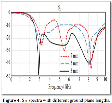
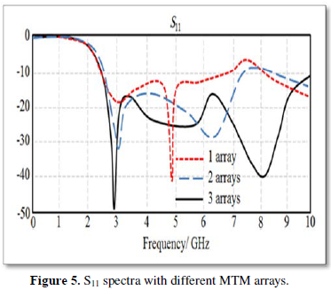
The antenna structure is based on a partial ground plane to obtain significant bandwidth enhancements. In Figure 4, the effect of the ground plane length on the matching impedance is realized with the S11 spectra. It is found that the antenna shows the best matching bandwidth at 7 mm from the antenna centre. This is due to the effects of fringing from the ground plane edges with respect to the patch edges.
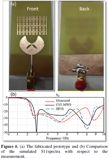
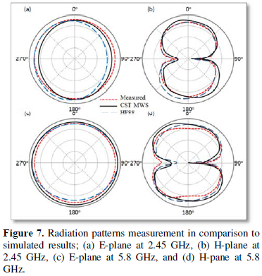
The proposed antenna performance is validated numerically before realize the prototype fabrication and perform the experimental measurements. Then the proposed antenna is fabricated using chemical etching processing. The fabricated antenna is shown in Figure 6a with MTM structure. The numerical validation is conducted with HFSS software package [15] to evaluate the S11 spectrum and the radiation patterns at 2.45 GHz and 5.8 GHz. As seen in Figure 6b, the obtained results from the CST MWS software package agree excellently with those obtained from the HFSS simulations. It is found that the proposed antenna shows excellent matching, |S11|<-10 dB, for the entire band from 2.38 GHz up to 10 GHz. When the experimental measurements are conducted with a Vector Network Analyzer (VNA) of Vector star MS4642A Series, the antenna shows excellent matching with entire band from 2.4 GHz up to 10 GHz.
CONCLUSION
- Elwi TA, Al-Rizzo HM, Al-Naiemy Y, Khaleel HR (2011) Miniaturized micro strip antenna array with ultra-mutual coupling reduction for wearable MIMO systems. IEEE International Symposium on Antennas and Propagation.
- Elwi TA, Hamed MM, Abbas Z, Elwi MA (2014) On the performance of the 2D Planar metamaterial structure. Int J Electron Commun 68: 9846-9850.
- Zhang Z, Satpathy S (1990) Electromagnetic wave propagation in periodic structures: Bloch wave solution of Maxell’s equations. Phys Rev Lett 65: 2650-2653.
- Elwi TA (2012) A further investigation on the performance of the broadside coupled rectangular split ring resonators. Prog Electromagn Res Lett 34: 1-8.
- Elwi TA, Al-Rizzo HM, Bouaynaya N, Hammood MM, Al-Naiemy Y (2011) Theory of gain enhancement of UC–PBG antenna structures without invoking Maxwell’s equations: An array signal processing approach. Prog Electromagn Res 34: 15-30.
- Elwi TA, Al-Rizzo HM, Rucker DG, Song F (2009) Numerical simulation of a UC-PBG lens for gain enhancement of micro strip antennas. Int J RF Microwave Comput Aided Eng 19: 676-684.
- Elwi TA, Al-Rizzo HM, Khaleel HR (2010) Gain enhancement of micro strip antennas using UC-PBG lens. Prog Electromagn Res Sym (PIERS) 2011.
- Schantz H (2003) Introduction to ultra-wideband antennas. Ultra Wideband Systems and Technologies. IEEE Conference.
- Schantz H (2004) A brief history of UWB antennas. Aerospace Electronic Systems Magazine. IEEE 19: 22-26.
- Elwi TA (2018) A slotted lotus shaped micro strip antenna based an EBG structure. J Material Sci Eng 7: 1-15.
- (2010) CST Microwave Studio. 10th version.
- Elwi TA, Imran AI, Alnaiemy Y (2015) A miniaturized lotus shaped micro strip antenna loaded with EBG Structures for high gain-bandwidth product applications. Prog Electromagn Res C 60: 157-167.
- Imran AI, Elwi TA (2017) A cylindrical wideband slotted patch antenna loaded with frequency selective surface for MRI applications. Eng Sci Technol Int J 20: 990-996.
- Elwi TA (2017) A miniaturized folded antenna array for MIMO applications. Wireless Pers Commun 98: 1871-1883.
- (2005) High Frequency Structure Simulator HFSS. 14th version, Ansoft Corporation.
")